MODULE THREE: PATTERN VS. SURFACE
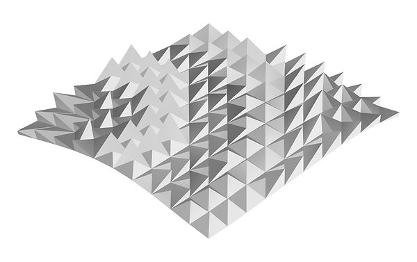

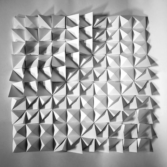
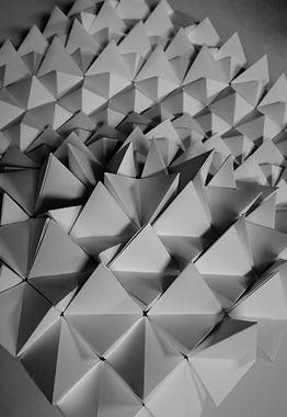
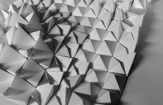
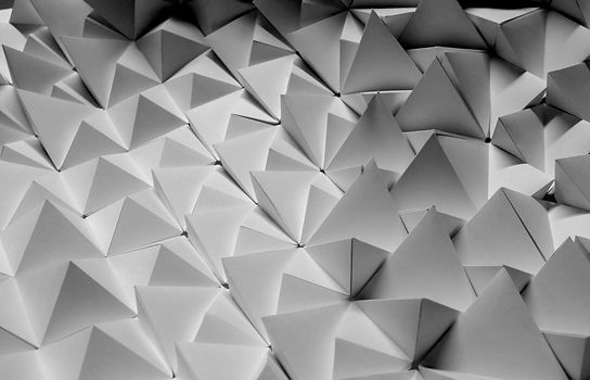
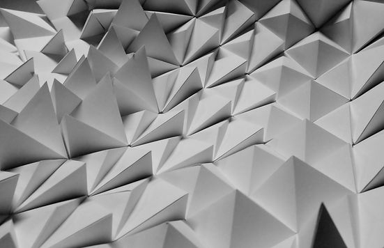
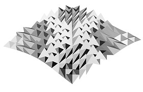
The inspiration behind my surface is the movement of the water when supplied energy, creating ripples as waves travel outward. I derived my pattern from six module types that consist of one to two pyramids in each. By using simple geometry, I aimed to focus on how they interact as a surface to create a wave-like motif rather than the complexity of the individual modules.


RHINO 6
-
Opened the base terrain in Rhino 6
-
Created layers (Base Terrain, Base Grid, Offset Grid, 3DPanel)
-
DupEdge
-
Moved the duplicated edge that it was beside the base terrain
-
NetworkSrf
-
PtGridSurfaceDomainNumber (Grid size 10)
-
ChangeLayer (Selected the new grid and changed the layer to Base Grid)
-
Created 3 curved lines that mimicked a ripple effect from the South West corner of the grid
-
PtOffsetGrid (Curve Attractor - towards)
-
ChangeLayer (Selected the offset grid and changed the layer to Offset Grid)
-
Rectangle (59.4 x 59.4)
-
Added lines and points in different corners to create different variations
-
Offset the point using the gumball tool (Offset to 59.4 and 30)
-
Exploded Lines
-
ExtrudeCrvToPoint
-
Grouped individual modules using Group
-
Meshed modules using Mesh
-
Joined the meshed modules using Join
-
PtPanel3DCustomVariable (Point Attractor - clicked the South West corner)
-
MeshtoNURB
-
Created new sublayers to 3DPanel (Column No. 1-10)
-
Created new sublayers to column layers (Srf, Cut, Fold)
-
Join 2-3 Modules
-
UnrollSrf
-
ConvertDots
-
DupEdge
-
ChangeLayer (Moved the duplicated edge to the Fold layer)
-
PtTabs
-
ChangeLayer (moved the tabs to the Cut Layer)
-
Repeated for all columns
-
Exported each module as an individual illustrator file 1mm to 1mm from top view


Iteration One- Singular Curve Attractor
Iteration Two - Three Curve Attractors
Iteration Three - Two Colliding Curve Attractors

Final Design - Three Curve Attractors
ILLUSTRATOR
-
Opened the exported unrolled panels
-
Copied the net from each illustrator file onto a new file consisting of twenty-two A3 artboards
-
Deleted stray lines from the mesh
-
Changed the stroke weight of the cut and fold lines to 0.5pt and 0.25pt respectively
-
Shifted the positioning of numbers that they were all within the boundaries of the cut lines
-
Labelled each net with the column and module number
-
Exported the Illustrator file as a PDF
-
Printed on A3 paper at 100% scale

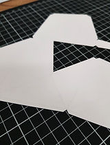
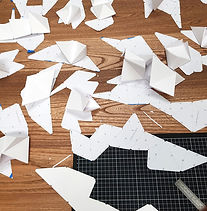
CONSTRUCTION
I created a prototype of my model using 200gsm cartridge paper prior to constructing it out of the ivory card. This allowed me to make mistakes, and gauge the amount of time it would take to make the real model.
The lessons I learnt were:
-
To print at a scale of 100% rather than selecting fill page, or fit to page
-
To tape the grid to the template
-
Cut out all nets and place them on the material to maximise the usage of each sheet
-
To cut small tabs first then the long strips to improve the stability of the net when cutting
-
To keep the blade of the knife sharp
-
Not to press too hard when scoring lines as that cut the paper
-
To fold the modules to form a general shape before glueing
-
To score and fold in the right direction
-
To glue/tape along the entirety of the tab to ensure the corners were properly secured
-
To mark off a 10x10 grid of paper to keep track of which modules were completed
-
To align the modules precisely when attaching them to one another
-
To handle the modules with care when folding and manoeuvring them as they are delicate and can rip


When completing my final model, the process I used was to:
-
Cut out all the nets from the A3 printed templates roughly
-
Arranged the nets onto the sheets of ivory card, securing them with small strips of painters tape
-
Cut out the template/ivory card to make individual pieces to place on the cutting mat
-
Cut the small grooves of the tabs first, then larger flat lines with a ruler
-
Removed the template once the cut lines were complete and lightly scored the fold lines, being mindful of the direction of the folds
-
Taped the tabs to each other using double-sided tape
-
Constructed the grid column by column, connecting them as a strip
-
Taped the strips together, using clips to hold them into place


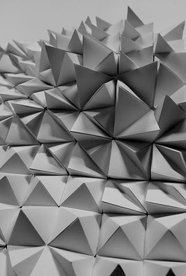
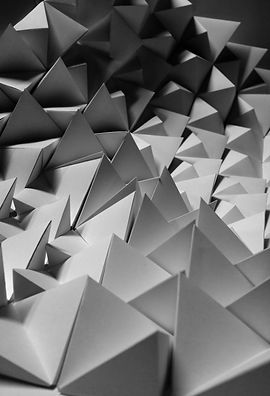
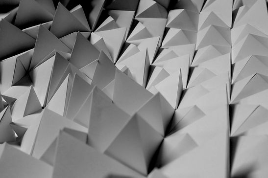
PHOTOGRAPHY
To photograph my model, I used a FujiFilm X100s with my aperture set to 8. I used sheets of A1 cartridge paper to create my backdrop and lit the photo studio with torches. To achieve the photo quality I wanted, I adjusted the levels and contrast on each of the photos and added a black and white filter. To smooth imperfections and lines on my backdrop I used the spot healing tool and the patch tool. Overall, I aimed to capture the gradient between the modules and their interaction with adjacent pyramids as well as the diagonal movement and undulation of height.